How Does a Control Valve Work? (The Simplest Guide for Techs)
A control valve is a machine that controls the flow of fluid by reacting to signals from building management systems or system managers. An actuator device controls the valve by receiving electrical, gas, or hydraulic signals and changing the position of the valve with those signals. When the actuator moves the valve stem, it changes the size of the hole that fluid can pass through. This can change the temperature, pressure, or flow rate. Because they can be controlled so precisely, control valves are important parts of oil and gas operations, pipeline systems, and industrial processing plants where managing flow correctly has a direct effect on how well they work and how safe they are.

The Basics of Control Valves: How They Work and What They Do?
Control valves are the last piece of control in automated process systems. They connect digital control messages to the management of real fluids. Engineers and procurement managers can make better decisions that improve system stability and lower running costs when they understand how they work at their core.
Essential Components and Operating Principles
There are three main parts to every control valve that work together. The flow path and the internal trim parts that come into direct touch with the process fluid are inside the valve body. The actuator applies the mechanical force that moves the valve, and the positioner checks that the valve is moved correctly by comparing the control signal to the valve's real position.
When a process manager sees that the desired setpoint has been crossed, the working sequence starts. The processor tells the valve positioner what to do, and the valve positioner tells the actuator how to move the valve. It changes the flow area through the valve, which changes the flow rate until the process variable goes back to its original value.
Control Signal Types and Response Characteristics
Modern control valves can react to different types of signals, based on the needs of the system and the location where it is installed. Electronic outputs from 4 to 20 mA or 0 to 10 VDC allow for precise control and great system integration in digital systems. Pneumatic signs, which are usually between 3 and 15 PSI, work reliably in dangerous places where electricity signals could be dangerous.
How changes in flow affect changes in valve position depends on how the valve responds. Linear characteristics change the flow rate proportionally as the valve moves, while equal percentage characteristics keep the control working the same way even when the process conditions change. Because they open quickly, they can set up flow quickly, so they're better for on/off uses than changing control.
Differentiation from Other Valve Types
When it comes to how they are designed and what they can do, control valves are very different from separation valves like gate or ball valves. Control valves value accurate flow modulation and stable operation throughout their entire trip range, whereas isolation valves are designed for tight shutoff and minimal pressure drop when fully open.
These different objectives can be seen in the style of the internal trim. The plugs and seats in control valves are formed in a certain way so that the flow is reliable and there is little vibration or cavitation. The materials and production tolerances also show that the positioning must be accurate over millions of rounds of use.
Types of Control Valves and Their Functions
Different valve types are needed in industrial settings because of the different process conditions, fluid qualities, and performance needs. Choosing the right type of valve has a direct effect on how well the system works, how much upkeep it needs, and how much it costs to run in the long run.
Globe Valve Configurations and Applications
The most common type of control valve is the globe valve, which is great at throttling and has reliable flow properties. When the valve plug moves in a straight line with the flow, it controls the flow precisely and with little dead band or hysteresis.
Single-seated globe valves can close tightly, but they need bigger actuators because the force from the process pressure isn't balanced. By balancing most of the process forces, double-seated designs lower the size of the actuator that is needed. However, they usually can't achieve tight cutoff because the two plugs expand and contract at different rates.
There is a cylinder-shaped cage inside cage-guided globe valves that moves the plug and provides more flow paths. Compared to standard globe valve designs, this one is more stable and makes less noise, which makes it perfect for high-pressure drop uses.
Rotary Valve Technologies
The spherical closing element on a ball valve can rotate 90 degrees between fully open and closed places, making it great for situations that need to work quickly and tightly. Certain types of ball valves have carefully shaped flow paths that allow for good control while still having the sealing benefits of full ball designs.
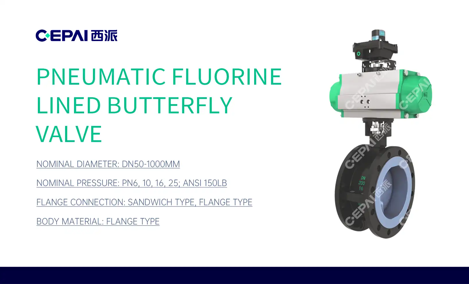
Butterfly valves are an affordable way to move big lines where weight and room are important factors. The disc moves back and forth in the flow stream, causing a pressure drop that changes a lot depending on where the valve is positioned. Disc profiles and seat materials used in modern butterfly valves are more advanced, which lets them be used in harsher working situations.
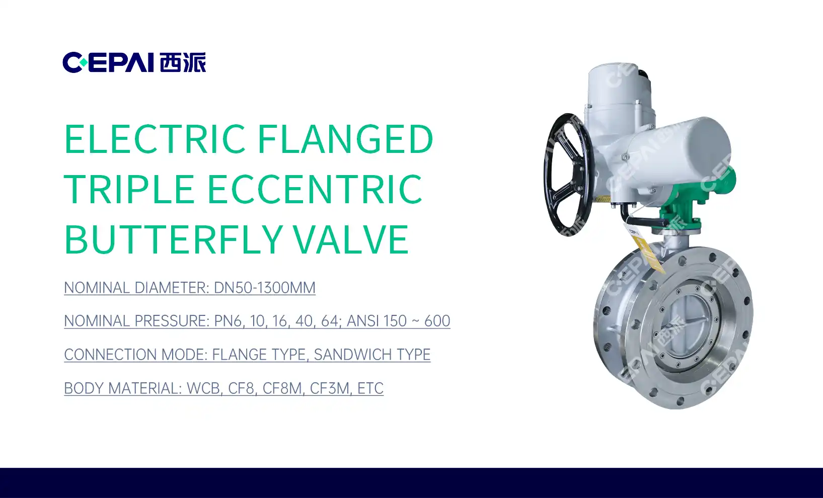
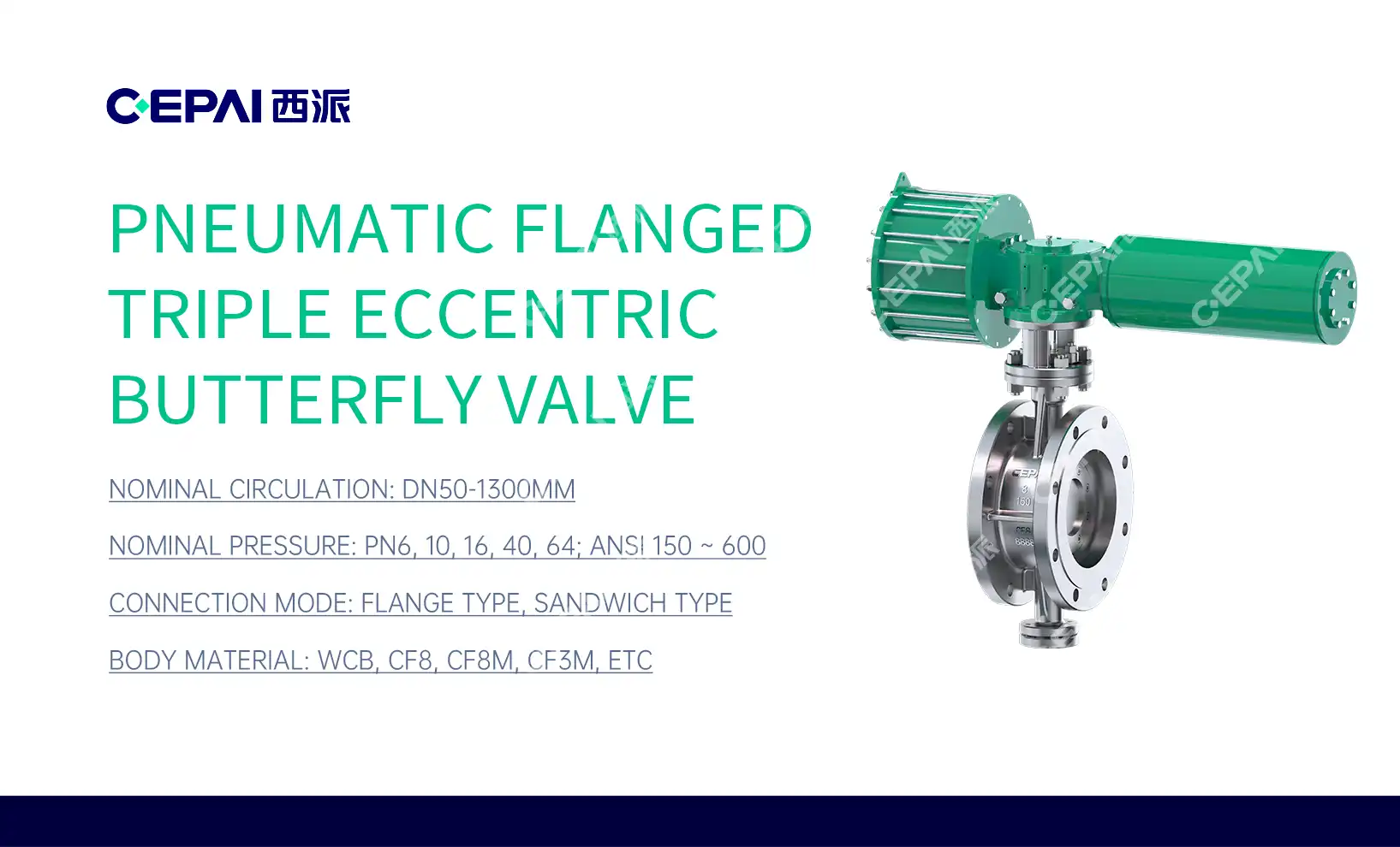
Eccentric disc control valve take the best features of both globe and rotating valves: they close well and are small. The disc slides away from the seat along a cam path before it rotates. This eliminates friction and wear and gives the device great shutdown capability.
Actuator Technologies and Selection Criteria
Pneumatic actuators are the most common type of control valve because they are fail-safe, respond quickly, and don't need much upkeep. When the air supply goes out, spring-return designs move the valve to a safe position automatically. This is a very important safety feature for process systems.
Electric lifters can precisely position things and don't need instrument air systems, which makes them a good choice for places that are hard to reach or that are sensitive to the environment. Using advanced motor control algorithms in modern electric designs makes them run smoothly and consistently, while also efficiently managing power use.
When it comes to uses with big valves or high pressures, hydraulic motors produce the most force. Most of the time, they are used in specific tasks where pneumatic or electric options can't provide enough force or reaction.
How to Size and Select the Right Control Valve for Your Application?
The right valve size allows for the best process control and avoids the performance and efficiency issues that come with valves that are too big or too small. In order to make a choice, the selection process needs to carefully look at the process conditions, the control needs, and the economic factors.
Flow Coefficient Calculations and Sizing Methodology
The flow coefficient (Cv) is the basic factor used to size control valves. It is the amount of water flowing through the valve at 60°F per minute that causes a 1 PSI drop in pressure across the valve. To do accurate Cv estimates, you need to know a lot about the process, like the flow rates, pressures, temperatures, and qualities of the fluid.
The basic equation for figuring out the size of a liquid is Cv = Q × √(SG/ΔP), where Q is the flow rate, SG is the specific gravity, and ΔP is the pressure drop. It's harder to figure out the right size for a gas because you have to take into account things like compressibility, pressure recovery, and situations where the flow might be slowed down.
Under normal conditions, the chosen valve should be between 20% and 80% open. This will give you enough range for process control while still allowing for process problems. If you size the valve so that it stays wide open under regular conditions, you can't control it, and the process may become unstable.
Pressure Drop Considerations and System Analysis
Control valves should take up 25–50% of the total drop in system pressure to keep control working well and lessen the effects of changes in system pressure. When the pressure drops too low, it can make it hard to control, and when it drops too high, it can cause problems with cavitation, popping, or noise.
All parts of the system, like pipes, fittings, heat exchanges, and other tools, must be taken into account in the system pressure drop analysis. When the flow rate is at its highest, the total system capacity minus the pressure drops of all the other parts equals the available pressure drop for the control valve.
When the pressure at the vena contracta (the lowest place of pressure) drops below the fluid vapor pressure, cavitation happens. This is followed by a violent vapor bubble burst as the pressure rises further downstream. The right way to size something includes figuring out the cavitation index and choosing valve trim designs that keep this from happening as much as possible.
Material Selection and Environmental Compatibility
Materials used for valve bodies must not rust when exposed to process fluids and must also keep their mechanical strength at high temperatures and high pressures. Carbon steel is a cheap option for non-corrosive tasks, while stainless steel types offer a wider range of chemical compatibility at a slightly higher cost.
Exotic metals like Hastelloy, Inconel, or duplex stainless steels can be used in the harshest chemical conditions, but they need to be carefully weighed against their costs. Because they are directly exposed to fast-moving flow streams, trim materials often need better rust protection than body materials.
Both choosing the right material and adjusting for thermal growth are affected by temperature. For services that involve high temperatures, you might need special trim materials and body shapes that can handle thermal growth while still keeping the integrity of the seal. For uses at low temperatures, materials need to be strong enough to withstand impacts and heat shock.

Maintenance and Troubleshooting Tips for Control Valves
Proactive repair practices increase the dependability of control valves while reducing unexpected downtime and the production costs that come with it. Maintenance plans that are well-thought-out balance the number of inspections with the needs of the business while focused on finding problems early on.
Routine Inspection and Preventive Maintenance
Regular visible checks are the first step in effective maintenance programs for control valve. They find external leaks, strange vibrations, or strange noise patterns. The most common type of upkeep is making changes to the packing. This needs to be done carefully so that the system works without leaks and there isn't too much stem friction.
Maintenance requirements for gas and electric actuators are very different. For pneumatic systems, the air filter needs to be changed, the lubricator needs to be adjusted, and positioners and tools need to be calibrated on a regular basis. Electric actuators need to have their motor brushes checked, their gears oiled, and their limit switch settings and motor safety factors checked.
Positioner calibration makes sure that the valves are correctly positioned across the entire working range while keeping the reaction properties stable. These days' smart positioners can diagnose problems as they happen, so they can be fixed before they mess up the process or put people in danger.
Common Problems and Diagnostic Procedures
Valve sticking usually happens when process buildup forms on trim surfaces, actuator force isn't enough, or packing needs to be adjusted. The first step in systematic fixing is to test the stroke to see if the issue is with the valve assembly or the actuator system.
Leaking inside through the valve seat could mean that the trim is damaged, there is foreign matter in the system, or heat effects are stopping the valve from sitting properly. Using portable tools to test for seat leakage gives numbers that help with choices about whether to repair or replace.
Problems with hunting or movement are often caused by mistuning the positioner, not having enough stiffness in the actuator, or how the process interacts with other control loops. To find an answer, you need to carefully look at the whole control loop, which includes the dynamics of the process, how the processor is tuned, and how the valves respond.
Repair Versus Replacement Decision Analysis
Economic analysis of repair vs. replacement considers both direct and secondary costs are taken into account. These include changes in reliability, longer maintenance intervals, and better performance capabilities. Simple fixes, like replacing the packing or fixing up some trim, usually give great returns on investment.
When doing major repairs like replacing a lot of trim or redoing an actuator, you should carefully compare the cost of those fixes to the cost of buying new equipment. Modern valves are often made with better materials and design features that make them worth replacing even when they can still be fixed properly.
Working with qualified providers makes sure that you can get real replacement parts and professional help, and the guarantee coverage stays the same. Having established ties with dependable control valve manufacturers gives you ongoing help for the whole lifecycle of the equipment.
Conclusion
Technical workers can make decisions that improve process performance while lowering running costs when they understand how control valves work. From basic working principles to complex selection criteria, every part is important for a good implementation and long-term operation that you can rely on.
There are many types of valves and control technologies that can be used to meet almost any application need. The right size and material choice will ensure the best performance in any given working environment. Maintenance that is done proactively extends the life of machinery and stops costly process interruptions.
Strategic methods to buying things that balance technical needs with business needs help reach practical goals while keeping supply chain risks under control. New technologies and changing industry standards make it possible to improve performance and lower costs by carefully choosing tools and forming partnerships with suppliers.
FAQ
What is the main difference between a control valve and a shut-off valve?
Using special trim designs and actuators that allow exact placement, a control valve changes the flow precisely over its entire trip range. When fully open, shut-off valves work best for tight sealing and minimal pressure drop, but they can't always be placed in a safe middle position for flow control purposes.
How do I determine the correct Cv size for my application?
For CV sizing, you need correct process data like maximum flow rates, working pressures, fluid properties, and the amount of pressure drop that is available. The chosen valve should normally be between 20 and 80% open so that it has a good control range and can still adapt to changes in the process.
What causes control valve hunting and how can it be resolved?
Valve hunting usually happens because the positioner isn't tuned right, the process interacts with the valve, or the actuator isn't strong enough. To find an answer, the whole control loop has to be carefully looked at. This includes the tuning factors for the controller, the way the valves respond, and how the process moves.
Partner with CEPAI for Superior Control Valve Solutions
CEPAI offers top-notch control valve technology backed by a full set of API certifications, such as API 6A, API 6D, and API 16C. Our regulating valves, throttle valves, and wellhead control systems meet the strict needs of oil and gas operations while offering outstanding dependability and performance. CEPAI is a reliable company to buy control valves from for important process uses because they have a lot of experience with high-pressure settings and corrosive conditions. Email our expert team at cepai@cepai.com to talk about your unique needs and find out how our advanced valve solutions can help your business run more smoothly.

References
Smith, R.W. "Control Valve Handbook: Fourth Edition." Instrument Society of America, 2019.
Johnson, M.A. and Thompson, K.L. "Process Control Valve Selection and Sizing." Chemical Engineering Progress, Vol. 118, No. 3, 2022.
Anderson, P.C. "Fundamentals of Control Valve Technology for Oil and Gas Applications." Petroleum Engineering Journal, 2021.
Williams, D.R. and Chen, L. "Advanced Materials for Control Valve Applications in Corrosive Environments." Industrial Valve Technology Quarterly, Vol. 45, No. 2, 2023.
Brown, J.S. "Predictive Maintenance Strategies for Control Valves in Process Industries." Maintenance Engineering Handbook, 2020.
Taylor, R.M. "Economic Analysis of Control Valve Selection and Procurement." Process Engineering Economics Review, Vol. 12, No. 4, 2022.
_1746598525968.webp)
Get professional pre-sales technical consultation and valve selection services, customized solution services.

About CEPAI